This post is older than 2 years and might not be relevant anymore
More Info: Consider searching for newer posts

Custom waveform generation in two pins

Hello,

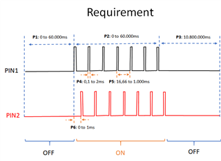
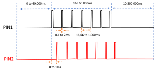
Considering the waveforms in the following chart, which will be the best approach to keep the power consumption as low as possible?

Specifically, which peripheral is suggested (i.e. pwm, timer, ppi)?

The two (2) waveform are identical, except for the delay between (0 to 2ms).

Thanks
Parents
  • Hi,

    the most power-saving approach is an RTC peripheral that would control two GPIOTE channels via PPI.

  • If the waveform is more or less static and don't require higher accuracy than 30.51µs, the RTC + GPIOTE is the best choice. 

    If the waveform is constantly changing and you have strict timing requirements the PWM peripheral will be best.

    Can you share more information on the nature of your signals? 

  • True, I think your approach is correct, but I think you still need the initial condition of the GPIOTE pin in order for the toggle to work as intended.

    Please, may you clarify which part is still needed? I though I already put the initial conditions with the function nrf_drv_gpiote_out_init and the macro GPIOTE_CONFIG_OUT_TASK_TOGGLE.

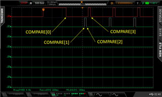
    About the RTC0 and COMPARE, very good catch!! After changing to RC2, the waveform is as expected, except the initial pulse, which I still need to set in order to use the solution. Is very important the output pins comply with the width defined. It will be used in external switch for actuators.

    Please, could you give a suggestion in order to set the initial pulse width (PIN1)?

    Thanks again for your support in this issue!

  • Hi , I worked on the period counting using the timer and compare function. The implementation worked as suggested. Thanks again for that!

    I only have the issue about the initial pulse width, which is around 1ms, when I need 0.1ms. Do you think, there is a way to reduce that pulse width? In case not, the PWM will be the only solution?

    The application could have an error in the pulse width of ~30us, but in this case the error is around ~1000us, which is too much.

    Thanks

    PS: I deleted the previous reply because was a false positive (I didn't fix the initial pulse width)

  • You can configure RTC to clear with the end of second channel pulse and set initial level to 0 for both channels, so your sequence will be aligned to the end of period (there will be some delay before the first pulse though)

  • Hi , thanks again for your feedback. Your suggestion is great. In this application the position of the first pulse could be delayed at the beginning. 

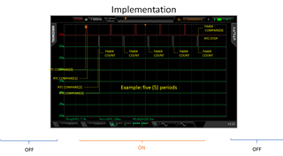
    I just implemented and is working as expected. Below the waveform for future reference. 

    Regarding the other two segments (OFF left and OFF right) do you have a suggestion, again trying to keep the power as low as possible? 

    Thanks

  • Hi again, just a small note to mentioned that the phases OFF (pre and post) were implemented using the app_timer. Perhaps, using the RTC with a comparator (+interruption for setup ON phase) will be a better approach for power consumption but I still need to check overall resources.

    In any case, the phase ON was very power sensitive.

    Thanks all for your feedback!

Reply
  • Hi again, just a small note to mentioned that the phases OFF (pre and post) were implemented using the app_timer. Perhaps, using the RTC with a comparator (+interruption for setup ON phase) will be a better approach for power consumption but I still need to check overall resources.

    In any case, the phase ON was very power sensitive.

    Thanks all for your feedback!

Children
No Data
Related