Hi Dev Team,
I was working with the nRF9160 and started off with the basic UART sample found here : https://github.com/Rallare/fw-nrfconnect-nrf/tree/nrf9160_samples/samples/nrf9160/uart
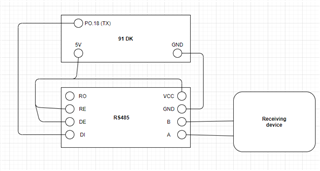
I wanted to configure the UART_1 to connect to an external sensor, and I followed some links : https://devzone.nordicsemi.com/f/nordic-q-a/45476/connecting-uart1-to-a-periph-on-nrf9160-dk/178988#178988, https://devzone.nordicsemi.com/f/nordic-q-a/57199/using-the-nrf9160-to-send-and-receive-data-over-rs485-using-uart and changed the prj.conf file and the overlays file.
prj.conf:
CONFIG_NEWLIB_LIBC=y
CONFIG_LIBLIGHTMODBUS=y


CONFIG_SERIAL=y
CONFIG_TRUSTED_EXECUTION_NONSECURE=y
CONFIG_UART_INTERRUPT_DRIVEN=y
CONFIG_MAIN_STACK_SIZE=4096

CONFIG_COMPILER_OPT="-DNRFX_UARTE_ENABLED=1 -DNRFX_UARTE0_ENABLED=1"


CONFIG_UART_1_NRF_UARTE=y

CONFIG_UART_1_NRF_FLOW_CONTROL=y

#CONFIG_BOARD_NRF9160DK_UART0_ARDUINO=y

#CONFIG_BOARD_NRF9160DK_UART0_VCOM=n
nrf9160dk_nrf9160ns.overlay:
/* Needed to get NRF_PWMn defined. */
&pwm1 {
	status = "okay";
};

&pwm2 {
	status = "okay";
};

&pwm3 {
	status = "okay";
};


&uart1 {
	current-speed = <9600>;
	status = "okay";
	tx-pin = <1>;
	rx-pin = <0>;
	rts-pin = <14>;
	cts-pin = <15>;
};

&uart0 {
	current-speed = <9600>;
	status = "ok";
	tx-pin = <10>;
	rx-pin = <11>;
	rts-pin = <12>;
	cts-pin = <13>;
};
The same is defined as an nrf9160dk_nrf9160.overlay file in the SPM folder.
When I try to build my application, I get a Kconfig error regarding the CONFIG_UART_1_NRF_UARTE=y. Could you help me understand what more could be required to change for it to work for UART_0.
Regards,
Adeel.