Good day
Due to I am very new with NRF chips and I did not find direct answer on forum I require some clarification on that moment...
The task is to detect input pulse ( trailing edge ) of original length 2 us and extend it for <time_us>
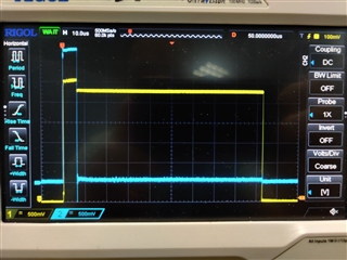
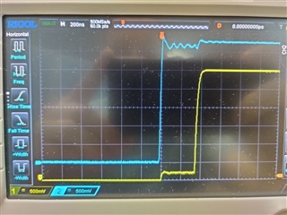
For now I have implementation that uses PPI channel: GPIOTE input event lowToHigh + GPIOTE output task TOGGLE( init_low ). When I detect edge -> toggle task fires ( output becomes high ) -> I nrf_delay_us( <time_us> ) in in_event_handler and trigger task manually nrf_drv_gpiote_out_task_trigger( out_pin ) -> pin becomes low. Edge trigger delay is acceptable and is about 400 ns: blue - input signal, yellow - output
I plan to improve this implementation with hw timer + PPI to produce <time_us> delay with falling edge
But the question is whether it is possible to implement this using only one pin ?
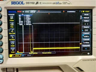
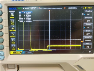
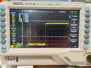
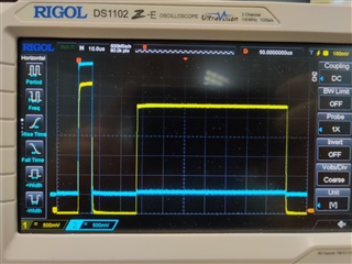
I successfully get trailing edge detection but when I re-configure input pin for output inside in_event_handler and produce extended pulse I get such picture. Input and output pins are connected with resistor so we get original pulse -> "falldown" while re-configuring -> high level
#if (_PROLONG_WITH_2_PINS)
static const nrf_drv_gpiote_out_config_t m_txir_out_config = GPIOTE_CONFIG_OUT_TASK_TOGGLE(false );
#else
static const nrf_drv_gpiote_out_config_t m_txir_out_config = GPIOTE_CONFIG_OUT_SIMPLE( false );
#endif
static const nrf_drv_gpiote_in_config_t m_txir_in_config = {
    .sense = NRF_GPIOTE_POLARITY_LOTOHI,
    .pull = NRF_GPIO_PIN_PULLUP,
    .is_watcher = true,
    .hi_accuracy = true,
    .skip_gpio_setup = false,
};

static void configure_txir_pin( bool input);

static void in_pin_handler(nrf_drv_gpiote_pin_t pin, nrf_gpiote_polarity_t action) {
    UNUSED_PARAMETER( pin );        /* only one pin event is enabled - no need to distinguish for now */
    UNUSED_PARAMETER( action );

#if( _PROLONG_WITH_2_PINS)
    nrf_delay_us( 70 );
    nrf_drv_gpiote_out_task_trigger( TXIR_OUT_PIN );
#else
    configure_txir_pin( false );
    nrf_drv_gpiote_out_set( TXIR_OUT_PIN );
    nrf_delay_us( 70 );
    configure_txir_pin( true );
#endif
}

void configure_txir_pin( bool input) {
    ret_code_t err_code;

    if( input ) {
        nrf_drv_gpiote_out_uninit( TXIR_OUT_PIN );
        err_code = nrf_drv_gpiote_in_init( TXIR_IN_PIN, &m_txir_in_config, in_pin_handler );
        APP_ERROR_CHECK(err_code);
        nrf_drv_gpiote_in_event_enable( TXIR_IN_PIN, true );
    }
    else {
        nrf_drv_gpiote_in_uninit( TXIR_IN_PIN );
        err_code = nrf_drv_gpiote_out_init( TXIR_OUT_PIN, &m_txir_out_config );
        APP_ERROR_CHECK(err_code);
    }
}


static void txir_prolong_setup() {
    ret_code_t err_code;
#if( _PROLONG_WITH_2_PINS )
    uint32_t gpiote_in_task_addr;
    uint32_t gpiote_out_task_addr;
    nrf_ppi_channel_t ppi_channel;


    nrf_drv_ppi_init();
#endif
    if( !nrf_drv_gpiote_is_init() ) {
        err_code = nrf_drv_gpiote_init();
        APP_ERROR_CHECK(err_code);
    }

    configure_txir_pin( true );

#if( _PROLONG_WITH_2_PINS )
    err_code = nrf_drv_gpiote_out_init(TXIR_OUT_PIN, &m_txir_out_config);
    APP_ERROR_CHECK(err_code);

    err_code = nrf_drv_ppi_channel_alloc(&ppi_channel);
    APP_ERROR_CHECK(err_code);

    gpiote_in_task_addr = nrf_drv_gpiote_in_event_addr_get(TXIR_IN_PIN );
    gpiote_out_task_addr = nrf_drv_gpiote_out_task_addr_get(TXIR_OUT_PIN );

    err_code = nrf_drv_ppi_channel_assign(ppi_channel, gpiote_in_task_addr, gpiote_out_task_addr);
    APP_ERROR_CHECK(err_code);

    err_code = nrf_drv_ppi_channel_enable(ppi_channel);
    APP_ERROR_CHECK(err_code);

    nrf_drv_gpiote_out_task_enable(TXIR_OUT_PIN);
#endif
}