This post is older than 2 years and might not be relevant anymore
More Info: Consider searching for newer posts

Input pulse width extend using GPIOTE / PPI

Good day

Due to I am very new with NRF chips and I did not find direct answer on forum I require some clarification on that moment...

The task is to detect input pulse ( trailing edge ) of original length 2 us and extend it for <time_us>

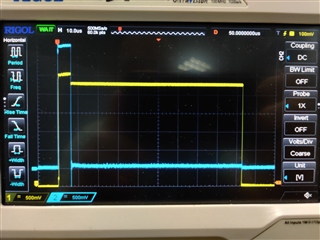
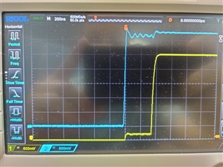
For now I have implementation that uses PPI channel: GPIOTE input event lowToHigh + GPIOTE output task TOGGLE( init_low ). When I detect edge -> toggle task fires ( output becomes high ) -> I nrf_delay_us( <time_us> ) in in_event_handler and trigger task manually nrf_drv_gpiote_out_task_trigger( out_pin ) -> pin becomes low. Edge trigger delay is acceptable and is about 400 ns: blue - input signal, yellow - output
        

I plan to improve this implementation with hw timer + PPI to produce <time_us> delay with falling edge

But the question is whether it is possible to implement this using only one pin ?

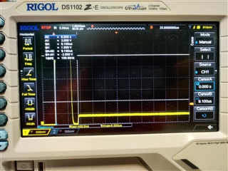
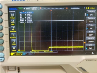
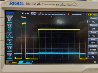
I successfully get trailing edge detection but when I re-configure input pin for output inside in_event_handler and produce extended pulse I get such picture. Input and output pins are connected with resistor so we get original pulse -> "falldown" while re-configuring -> high level
#if (_PROLONG_WITH_2_PINS)
static const nrf_drv_gpiote_out_config_t m_txir_out_config = GPIOTE_CONFIG_OUT_TASK_TOGGLE(false );
#else
static const nrf_drv_gpiote_out_config_t m_txir_out_config = GPIOTE_CONFIG_OUT_SIMPLE( false );
#endif
static const nrf_drv_gpiote_in_config_t m_txir_in_config = {
    .sense = NRF_GPIOTE_POLARITY_LOTOHI,
    .pull = NRF_GPIO_PIN_PULLUP,
    .is_watcher = true,
    .hi_accuracy = true,
    .skip_gpio_setup = false,
};

static void configure_txir_pin( bool input);

static void in_pin_handler(nrf_drv_gpiote_pin_t pin, nrf_gpiote_polarity_t action) {
    UNUSED_PARAMETER( pin );        /* only one pin event is enabled - no need to distinguish for now */
    UNUSED_PARAMETER( action );

#if( _PROLONG_WITH_2_PINS)
    nrf_delay_us( 70 );
    nrf_drv_gpiote_out_task_trigger( TXIR_OUT_PIN );
#else
    configure_txir_pin( false );
    nrf_drv_gpiote_out_set( TXIR_OUT_PIN );
    nrf_delay_us( 70 );
    configure_txir_pin( true );
#endif
}

void configure_txir_pin( bool input) {
    ret_code_t err_code;

    if( input ) {
        nrf_drv_gpiote_out_uninit( TXIR_OUT_PIN );
        err_code = nrf_drv_gpiote_in_init( TXIR_IN_PIN, &m_txir_in_config, in_pin_handler );
        APP_ERROR_CHECK(err_code);
        nrf_drv_gpiote_in_event_enable( TXIR_IN_PIN, true );
    }
    else {
        nrf_drv_gpiote_in_uninit( TXIR_IN_PIN );
        err_code = nrf_drv_gpiote_out_init( TXIR_OUT_PIN, &m_txir_out_config );
        APP_ERROR_CHECK(err_code);
    }
}


static void txir_prolong_setup() {
    ret_code_t err_code;
#if( _PROLONG_WITH_2_PINS )
    uint32_t gpiote_in_task_addr;
    uint32_t gpiote_out_task_addr;
    nrf_ppi_channel_t ppi_channel;


    nrf_drv_ppi_init();
#endif
    if( !nrf_drv_gpiote_is_init() ) {
        err_code = nrf_drv_gpiote_init();
        APP_ERROR_CHECK(err_code);
    }

    configure_txir_pin( true );

#if( _PROLONG_WITH_2_PINS )
    err_code = nrf_drv_gpiote_out_init(TXIR_OUT_PIN, &m_txir_out_config);
    APP_ERROR_CHECK(err_code);

    err_code = nrf_drv_ppi_channel_alloc(&ppi_channel);
    APP_ERROR_CHECK(err_code);

    gpiote_in_task_addr = nrf_drv_gpiote_in_event_addr_get(TXIR_IN_PIN );
    gpiote_out_task_addr = nrf_drv_gpiote_out_task_addr_get(TXIR_OUT_PIN );

    err_code = nrf_drv_ppi_channel_assign(ppi_channel, gpiote_in_task_addr, gpiote_out_task_addr);
    APP_ERROR_CHECK(err_code);

    err_code = nrf_drv_ppi_channel_enable(ppi_channel);
    APP_ERROR_CHECK(err_code);

    nrf_drv_gpiote_out_task_enable(TXIR_OUT_PIN);
#endif
}

Parents Reply Children
  • Hi,

    thanks for reply  - I did try to implement it in this way

    static const nrf_drv_gpiote_out_config_t m_txir_out_config = GPIOTE_CONFIG_OUT_SIMPLE( false );
    static const nrf_drv_gpiote_in_config_t m_txir_in_config = {
        .sense = NRF_GPIOTE_POLARITY_LOTOHI,
        .pull = NRF_GPIO_PIN_NOPULL,
        .is_watcher = false,
        .hi_accuracy = true,
        .skip_gpio_setup = false,
    };
    
    
    static void in_pin_handler(nrf_drv_gpiote_pin_t pin, nrf_gpiote_polarity_t action) {
        UNUSED_PARAMETER( pin );        /* only one pin event is enabled - no need to distinguish for now */
        UNUSED_PARAMETER( action );
    
    #if( !_PROLONG_WITH_2_PINS)
    /*  WORKS improperly
        configure_txir_pin( false );
        nrf_drv_gpiote_out_set( TXIR_OUT_PIN );
        nrf_delay_us( get_txir_pulse_width_us() );
        configure_txir_pin( true );
    */
        nrf_gpio_pin_set(TXIR_OUT_PIN );
        nrf_gpio_cfg(
                TXIR_OUT_PIN,
                NRF_GPIO_PIN_DIR_OUTPUT,
                NRF_GPIO_PIN_INPUT_DISCONNECT,
                NRF_GPIO_PIN_PULLUP,
                NRF_GPIO_PIN_H0H1,
                NRF_GPIO_PIN_NOSENSE);
    
        nrf_delay_us( get_txir_pulse_width_us() );
        nrf_gpio_pin_clear(TXIR_OUT_PIN );
        configure_txir_pin( true );
    #endif
    }
    
    void __used configure_txir_pin( bool input) {
        ret_code_t err_code;
    
        if( input ) {
            nrf_drv_gpiote_out_uninit( TXIR_OUT_PIN );
            err_code = nrf_drv_gpiote_in_init( TXIR_IN_PIN, &m_txir_in_config, in_pin_handler );
            APP_ERROR_CHECK(err_code);
            nrf_drv_gpiote_in_event_enable( TXIR_IN_PIN, true );
        }
        else {
            nrf_drv_gpiote_in_uninit( TXIR_IN_PIN );
            err_code = nrf_drv_gpiote_out_init( TXIR_OUT_PIN, &m_txir_out_config );
            APP_ERROR_CHECK(err_code);
        }
    }
    

    the problem is only in leading edge delay - there is profit but the problem is still exists. Now the output pin high level differs depending on how it is configured ( nrf_gpio_cfg() or nrf_drv_gpiote_out_init() )

    sdk_config.h

    #define GPIOTE_CONFIG_IRQ_PRIORITY 2

    below best and worst cases


    Sorry for delays - please take in account that it is a challenge for now to implement so main tasks may have influence

  • I can't get how your signals are put together.. does pulse source have open-drain output?

    At the end of pulse, you call nrf_gpio_pin_clear then configure_txir_pin - between them you have strong low level. You don't need to change pin state, only configuration. For predictable timings, it's probably better to use GPIOTE with NRF_GPIO_PIN_D0H1 output (not sure because I don't know your schematic).

  • Both plots reflect pin state - original pulse ( high one on the plots ) and generated ( low one but not complete ) have delay between leading edges and that is exactly what I was trying to show on plots

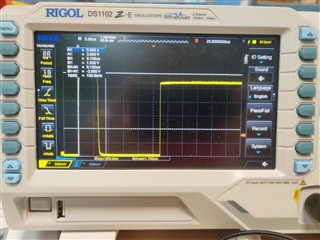
    The delay between leading edges ( ~25 us ) is time between GPIOTE edge detect event -> in_handler invocation ->  series of pin commands ( pin_set and pin_cfg ) before nrf_delay_us()

    The strong level you mentioned is caused because of delay when pin is not reconfigured to output - both plots describe leading edge ( despite of second one is too low to be high )

    But I use commented code

    #if( !_PROLONG_WITH_2_PINS)
        configure_txir_pin( false );
        nrf_drv_gpiote_out_set( TXIR_OUT_PIN );
        nrf_delay_us( get_txir_pulse_width_us() );
        configure_txir_pin( true );
    #endif
    

    I get next picture with the same schematic but with longer delay between leading edges

  • Yes, there are too much code executed in gpiote library before it calls your event handler. To make things faster, write your own high-priority interrupt handler instead of using library (though with running BLE stack you still get no guarantee that interrupt comes in time). Or you could configute pin as D0H1 and make a pulse with PWM hardware activated by GPIOTE event - I can't say for sure that it will work on the same pin but you can try.

Related