This post is older than 2 years and might not be relevant anymore
More Info: Consider searching for newer posts

nRF52840 Design Review Request

Hi,

We are developing nRF52840 based design with PCB antenna.

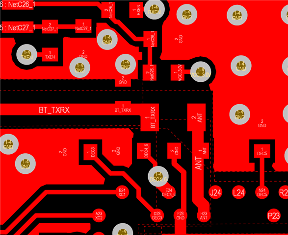
Please review the Schematic and PCB file.

Regards,

IrfanMeshtek_nRF52840_V1.0 PCB ANT_SCH.pdf20210607_nRF52840 Layout.PcbDoc

  • Hi Irfan

    I've taken a look at the design. The schematic is ok, no issues that I can see. For the layout, I have a few comments: 

    1 You should remove he cut outs on the inner layers. You need to have some shielding under the RF section and the inner ground layer can do that. 

    2. Move C13 closer to the ANT pin as the track is too long. Also move L2 and C2 closer to reduce the track length between the components. Something like this: 

    Else it looks good.

    best regards,

    Ketil Aas-Johansen

  • Hi,

    Thanks for the review and provide the feed back to us.

    I have a question on "1 You should remove he cut outs on the inner layers. You need to have some shielding under the RF section and the inner ground layer can do that. "

    Before few days i had share the other design with you and that time you had suggest below 

    "6. On PCBs with more than two layers, put a keep-out area on the inner layers directly below the antenna matching circuitry (components between device pin ANT and the antenna) to reduce the stray capacitances that influence RF performance.

    Suggest by Kaja "

    You can check my previous post "

    Review schematic and PCB layout.

    So please let me know the difference in this 02 comments. 

    Regards,

    Irfan

  • Hi,

    Please reply of my question.we are waiting to send pcb layout in Fabrication.

    Please reply.

    Regards,

    Irfan

  • Hi Irfan

    Sorry for the late reply, I've been away a few days. 

    The problem is that you have cutout on all layers under the RF section and at least one layer must be ground.  Layer 3 is split into power and VDD so you have only layer 2 as ground left.

    Parasitic capacitance to ground isn't a great problem on nRF52 devices. It used to be a problem on nRF51 devices since the matching network had more components. 

    cheers,

    Ketil

  • Hi,

    Thanks for the reply .Okay I will put Ground plane below at RF components for this design.

    Now what to do for my earlier design which pcb is ready with components assembly.which layout has no ground plane below the RF components.

    Suggest me what to do .Need to update PCB layout with ground plane below the RF components ???

    FYI will go for FCC for both the design

    Actually my earlier design also was review by the nordic devzone  which i was mention in my previous post.

    Regards,

    Irfan

Related