Hi,
I'm using app_ble_uart example using nrf52810 for nrf52810 UART RX & TX pins are (P0.15 - P0.14) while configuring using i got a problem with RX transmission ,when i changed to Rx pin as p0.15 the nrf52810 module is not working.
Hi,
I'm using app_ble_uart example using nrf52810 for nrf52810 UART RX & TX pins are (P0.15 - P0.14) while configuring using i got a problem with RX transmission ,when i changed to Rx pin as p0.15 the nrf52810 module is not working.
Hi,
I have some questions:
If i just change only (TX pin to P0.14) NRF52810 module is going to powered on its advertising the ble and it only transmitting the data .when if i change RX pin also even the NRF52810 module not going to powered on .
Here i changed the TX and RX pin in my code
static void uart_init(void)
{
    uint32_t                     err_code;
    app_uart_comm_params_t const comm_params =
    {
        .rx_pin_no    = 15,
        .tx_pin_no    = 14,
        .rts_pin_no   = RTS_PIN_NUMBER,
        .cts_pin_no   = CTS_PIN_NUMBER,
        .flow_control = APP_UART_FLOW_CONTROL_DISABLED,
        .use_parity   = false,
#if defined (UART_PRESENT)
        .baud_rate    = NRF_UART_BAUDRATE_115200
#else
        .baud_rate    = NRF_UARTE_BAUDRATE_115200
#endif
    };

    APP_UART_FIFO_INIT(&comm_params,
                       UART_RX_BUF_SIZE,
                       UART_TX_BUF_SIZE,
                       uart_event_handle,
                       APP_IRQ_PRIORITY_LOWEST,
                       err_code);
    APP_ERROR_CHECK(err_code);
}
Hi,
There is nothing special about P0.14 and P0.15, so we must look further to understand what is happening. Tw0 important questions:
_bhanu said:not working like its not going to "powered on" .
What exactly do you mean by this? Have you debugged to see which state the device is in?
HI,
Do you use any of the two pins for anything else in your firmware?
I didn't use those pins for any other purpose i only only used for TX & RX in my firmware.
How are this pins connected physically on your HW?
i connected TX pin of HW connected to FTDI to see weather the communication happens or not.
What exactly do you mean by this? Have you debugged to see which state the device is in?
when i mention RX pin as P0.15 the ble was not advertising and moreover which data i given to transmit is also not doing. this problem I'm facing only when i mention RX pin as P0.15
_bhanu said:i connected TX pin of HW connected to FTDI to see weather the communication happens or not.
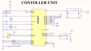
Can you share your schematics so that we can see if those pins are also connected to something else?
_bhanu said:when i mention RX pin as P0.15 the ble was not advertising and moreover which data i given to transmit is also not doing. this problem I'm facing only when i mention RX pin as P0.15
That is quite high-level, then. Have you tried to debug? What does that tell you? Are any APP_ERROR_CHECK's hit or something else?
happens or not.
That is quite high-level, then. Have you tried to debug? What does that tell you? Are any APP_ERROR_CHECK's hit or something else?
i already tried so, many times to debug but i didn't get any data while debugging
happens or not.
That is quite high-level, then. Have you tried to debug? What does that tell you? Are any APP_ERROR_CHECK's hit or something else?
i already tried so, many times to debug but i didn't get any data while debugging
Hi,
I do not see anything obviously problematic in the schematic.
_bhanu said:i already tried so, many times to debug but i didn't get any data while debugging
As long as the device is powered and nothing messes with the SWD lines, you should be able to get something out of the debugger. Can you explain how you debug and what you find (how little it may be)? By explaining (and showing) the issues you have while debugging in more detail, perhaps I can suggest what you can do to get around those problems. I assume you are able to erase and re-program the device? If so, the debug interface is working. Debugging must work in order to develop and test in any meaningful way, and debugging is only sensible way to move forward.
Hi,
i have a question is it required to pullup the RX pin in Custom board to work on that
Hi,
You need to ensure that the inputs are not floating. If the UART lines are always connected to another device on the board, and this always drives the input lines to the nRF ( Rx and optionally CTS), then there is no need for pullup(s). If not, you can enable the internal pullup. See this post.
Hi,
Hear my UART lines TX and RX are connected to "QUECTEL" module when the Quectel module is on nRF device working fine, when i turned of the Quectel module which is connected to UART then nRF is also going to turn off automatically.
Hi,
I see. Then there should not be a need for any pull resistors (and if you double-check and see that in some corner cases the inputs are floating, you can always just enable internal pullups on the nRF).