Hi,
I'm using app_ble_uart example using nrf52810 for nrf52810 UART RX & TX pins are (P0.15 - P0.14) while configuring using i got a problem with RX transmission ,when i changed to Rx pin as p0.15 the nrf52810 module is not working.
Hi,
I'm using app_ble_uart example using nrf52810 for nrf52810 UART RX & TX pins are (P0.15 - P0.14) while configuring using i got a problem with RX transmission ,when i changed to Rx pin as p0.15 the nrf52810 module is not working.
Hi,
I have some questions:
If i just change only (TX pin to P0.14) NRF52810 module is going to powered on its advertising the ble and it only transmitting the data .when if i change RX pin also even the NRF52810 module not going to powered on .
Here i changed the TX and RX pin in my code
static void uart_init(void)
{
    uint32_t                     err_code;
    app_uart_comm_params_t const comm_params =
    {
        .rx_pin_no    = 15,
        .tx_pin_no    = 14,
        .rts_pin_no   = RTS_PIN_NUMBER,
        .cts_pin_no   = CTS_PIN_NUMBER,
        .flow_control = APP_UART_FLOW_CONTROL_DISABLED,
        .use_parity   = false,
#if defined (UART_PRESENT)
        .baud_rate    = NRF_UART_BAUDRATE_115200
#else
        .baud_rate    = NRF_UARTE_BAUDRATE_115200
#endif
    };

    APP_UART_FIFO_INIT(&comm_params,
                       UART_RX_BUF_SIZE,
                       UART_TX_BUF_SIZE,
                       uart_event_handle,
                       APP_IRQ_PRIORITY_LOWEST,
                       err_code);
    APP_ERROR_CHECK(err_code);
}
Hi,
I do not see anything obviously problematic in the schematic.
_bhanu said:i already tried so, many times to debug but i didn't get any data while debugging
As long as the device is powered and nothing messes with the SWD lines, you should be able to get something out of the debugger. Can you explain how you debug and what you find (how little it may be)? By explaining (and showing) the issues you have while debugging in more detail, perhaps I can suggest what you can do to get around those problems. I assume you are able to erase and re-program the device? If so, the debug interface is working. Debugging must work in order to develop and test in any meaningful way, and debugging is only sensible way to move forward.
Hi,
i have a question is it required to pullup the RX pin in Custom board to work on that
Hi,
You need to ensure that the inputs are not floating. If the UART lines are always connected to another device on the board, and this always drives the input lines to the nRF ( Rx and optionally CTS), then there is no need for pullup(s). If not, you can enable the internal pullup. See this post.
Hi,
Hear my UART lines TX and RX are connected to "QUECTEL" module when the Quectel module is on nRF device working fine, when i turned of the Quectel module which is connected to UART then nRF is also going to turn off automatically.
Hi,
I see. Then there should not be a need for any pull resistors (and if you double-check and see that in some corner cases the inputs are floating, you can always just enable internal pullups on the nRF).
Hi,
I see. Then there should not be a need for any pull resistors (and if you double-check and see that in some corner cases the inputs are floating, you can always just enable internal pullups on the nRF).
Hi,
you can always just enable internal pullups on the nRF
I tried to do RX pin as internal pullup using "nrf_gpio_cfg_input(RX pin, NRF_GPIO_PIN_PULLUP)" but then also I'm facing same issue,
is their any alternative way to internal pullup the UART RX pin.
Hi,
If you enabled the internal pullups as described, then you have pullups so that should be good (and if the other device always drives the pins it is not even required). So I suggest you start looking in another direction.
I am not sure I have the full picture here. Can you elaborate more on which issue you are seeing now and in what way things are not working? Also, what have you found from debugging?
Hi,
Can you elaborate more on which issue you are seeing now and in what way things are not working?
as i said earlier I'm transferring and receiving the data through Quectel m66 module using NRF UART,
after the completion of transferring and receiving the data I'm going to turn off the Quectel module .
when i turn off the Quectel module NRF52810 also turning off automatically
what have you found from debugging?
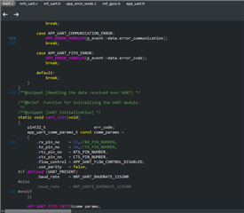
<error> app: ERROR 4 [NRF_ERROR_NO_MEM] at C:\nrf_sdk\nRF5_SDK_17.1.0_ddde560\examples\ble_peripheral\ble_app_uart\main.c:429
PC at: 0x0001A393
<error> app: End of error report
This is the error I found while debugging.
Aha, so you are simply seeing that an error check has caught an error. That is a very good starting point. What does your code look like around line 429 in your main.c? Most importantly, which function returned this error code (NRF_ERROR_NO_MEM)?
Hi,
What does your code look like around line 429 in your main.c?
Most importantly, which function returned this error code (NRF_ERROR_NO_MEM)?
I assume In "uart_event_handle(app_uart_evt_t * p_event)" function this error occurs