This post is older than 2 years and might not be relevant anymore
More Info: Consider searching for newer posts

nrf24l01+, pcb mifa antenna design

Hello guys,

I tried to design a pcb antenna for a nrf24l01+, since my company doesnt allow to buy cheap smd breakout board version from china anymore
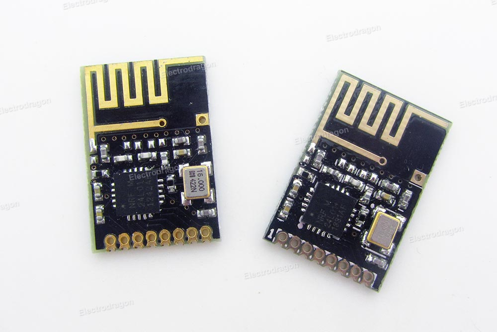
The pcb stats of the producer:

  • 2-layer FR4 1.55mm (61.023mil)  thickness, εr = 4.6
  • Copper thickness, 35μm (1.378mil)

What I used:

This results into following desgin block:


The antenna area is clear of any signals aswell as ground on top or bottom layer.

Since I have absolutly zero experience with RF antenna design I would like to have some opinions regarding my design.

Thanks so far,

Joe

Parents
  • Hey guys, Im back Slight smile

    the current state of me trying to copy the design is the following. I designed it as a design block in EAGLE in order to import it into my project later. Thats why GND-plane is not implemented yet.

    Had to find an other crystal which fits the requirements mentioned by AmbystomaLabs.
    So far the GND-plane is planned for the dotted area, whereas the antenna is planed to be free of GND or any other signals on top and bottom layer.  Anyway Im unhappy with this huge empty space on the left. I guess its okay to reduce the size, but Im unsure about the holes. Is it okay to remove them completely and basicly cut everything whats not needed on the left? By the way: Whats the intention behind placing all the holes? Whats their use? I cant find a clear pattern so for me it looks very random. Do I need some more holes to seperate the antenna from the rest of the pcb, which is not shown in the picture? Still learning about the whole RF design topic and I very appreciate all your advices.

    Thank you :)

  • Hello, and welcome back!

    This is starting to look good. 

    JoE1205 said:
    Anyway Im unhappy with this huge empty space on the left. I guess its okay to reduce the size, but Im unsure about the holes. Is it okay to remove them completely and basicly cut everything whats not needed on the left?

    The open area on the left should be used to add pads and/or GPIO pins for physical connection to flash/program/debug. Ref. the reference design I referred to in this comment, the image shows that there is a connector placed in the left side of the board. The holes which you mention are via-holes and are used to connect and ensure that the GND layers are connected. 

    I recommend that you remove the vias and finish your layout with components, GND-plane, and traces. Then send the layout to us, and we can help with adding vias. Have a look at this tutorial on Eagle from Sparkfun, and our tutorial on RF design.
    Kind regards,
    Øyvind

  • You need to turn off the thermals on the vias.  There should be a selection in your software that says something like "flood over vias". Only plated thru holes for leaded devices get thermals since this makes soldering easier.

    You can stitch under the crystal too.

    You forgot to put vias under the nRF. Not sure how many you can fit by looking at it.  But an X of 5 vias should probably be sufficient. Just make sure the annular rings are well inside of the edge of the pad. Then you let them flood with mask on the bottom layer and that effectively tents them.

    I normally also place a via directly behind or next to all shunt RF components.  The farther the ground via is away the worse the phase relationship of that part is to an ideal model.  If the ground is close by then the matching solution is a little more predictable.

  • More stitches and all without thermals, including crystal and nrf pad (managed to include 9 vias.)

  • Looks good.  The only thing left is the traces between RF components are rather narrow.  Now sometimes this is by design or sometimes it is just impossible to have characterized traces between the RF components or sometimes it just doesn't matter since the whole thing gets matched anyway.

    On the reference design the traces between the components on the nRF output match look to be about the same as the pad width.  This is a pretty standard practice that gives a less inductive trace while still meeting the trace/space spec for the board.

    Anyway, if you feel they are close to the reference designs for both the antenna and the nRF then run with it as is, otherwise I would fatten them up to closer to the width of the pad as long as you don't create spacing violations.

    After that make sure your DRC rules match your board vendors spec and run with it.  Looks fine to me.

  • I adjusted the width of all traces to the pads width without spacing violations.


    Thank you so much for guiding me through this.
    Not really looking forward to solder this since 0402 is really painful.
    Anyway I going to give reply when everything is tested and working perfectly obviously.

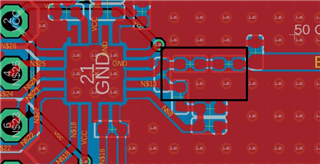
  • Remove some of the ground plane around the matching network components to reduce capacitance to ground, like this (inside the black rectangle)

    Then you're good 

Reply Children
Related