This post is older than 2 years and might not be relevant anymore
More Info: Consider searching for newer posts

nrf24l01+, pcb mifa antenna design

Hello guys,

I tried to design a pcb antenna for a nrf24l01+, since my company doesnt allow to buy cheap smd breakout board version from china anymore
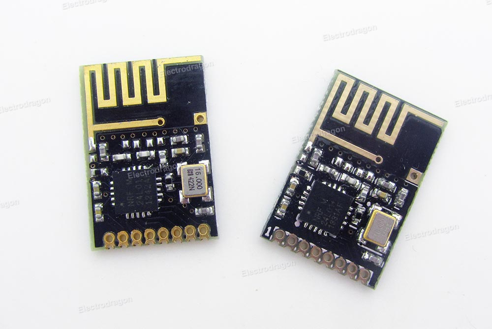
The pcb stats of the producer:

  • 2-layer FR4 1.55mm (61.023mil)  thickness, εr = 4.6
  • Copper thickness, 35μm (1.378mil)

What I used:

This results into following desgin block:


The antenna area is clear of any signals aswell as ground on top or bottom layer.

Since I have absolutly zero experience with RF antenna design I would like to have some opinions regarding my design.

Thanks so far,

Joe

Parents Reply Children
  • Hi guys,

    so i soldered everything as good as Im able to, anyway the communication with this module is very poor.

    For me there are 2 possible reasons:

    -----------------------------------------------

    1. Crystal:
    While soldering I noticed that the wiring for the crystal is wrong, so i had to solder it upside down onto the pcb ( isolated from it so the is no unintended connection between pcb and crystal). Im not sure if this affects the RF connection.

    2. My solder skills are to bad. I tried to check every connection direclty after soldering a component. Anyway the size is a big problem, so its hard to be sure that I get in touch with the pins of the components.

    -----------------------------------------------

    I assume that the design with the fixed crystal is correct, anyway the communication with this module is very poor. I rarely get a full functional connection at all, atleast sometimes its working. Most of the time I dont get a connection. Sometimes just for a millisecond.

  • Yeah, that is a drag that you got the footprint wrong on the crystal.  Always pay close attention to whether the spec's show bottom view or top view for the pins.

    That's probably a good place to start with the communications issue.  The extra wiring from flipping it over will change the load on the crystal and alter the resonant frequency. You can easily tune it back to nominal but you need some sort of spectrum analyzer to figure out how much the RF carrier is off.  There are cheap WiFi module based spectrum analyzers out there.  Normally around $100. Alternatively you can output HFCLK/2 through gpio and try to measure its frequency with an o-scope.  The problem with this is most o-scopes have lousy oscillators and you need to get the nominal frequency to +/-40ppm for BLE.

    Once you get that fixed you should verify the RF power output.  Easiest way is RSSI at one meter. Just put it in a link with a smartphone or something and look at the RSSI.  If you thumb around on the devzone you should find what people expect it to be for that chip.

  • Hi there, i'm currently working on the same project as yours. I just wonder if your board can work?

Related