Hello,
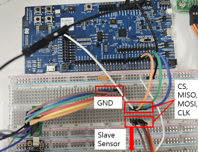
I am trying to exchange data with an external slave sensor via SPIM communication using the nRF5340DK.
I am currently facing two main issues:
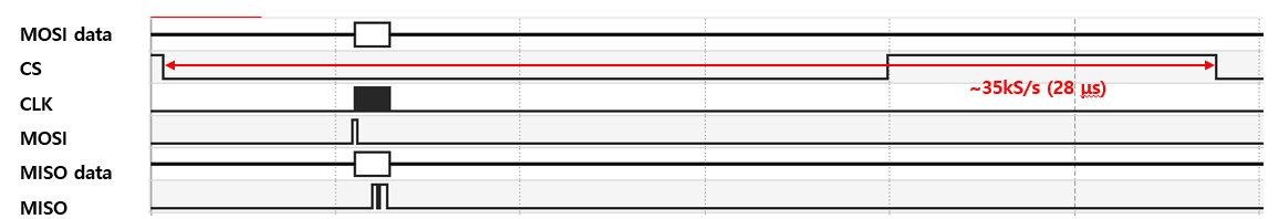
1.The spi_transceive() function takes too long to execute.
This is significantly reducing the effective data transfer rate.
I have also reviewed a Q&A from someone who pointed out a similar delay with spi_transceive().
( Time gap between each spi_transceive )
However, the solution suggested in that Q&A, which involved modifying spi configuration in the main.c, doesn't seem to be applicable to the nRF5340 as it resulted in an error
To clearly explain my situation, I have attached my main.c, overlay, and configuration files.
main.c
#include <zephyr/kernel.h>
#include <zephyr/device.h>
#include <zephyr/drivers/spi.h>
#include <zephyr/drivers/uart.h>
#include <zephyr/sys/printk.h>
#include <zephyr/drivers/gpio.h>
#include <stdio.h>
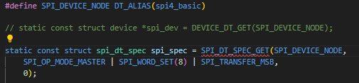
/* Get SPI device from devicetree */
#define SPI_DEVICE_NODE DT_ALIAS(spi4_basic)
static const struct device *spi_dev = DEVICE_DT_GET(SPI_DEVICE_NODE);
static const struct device *uart_for_data_tx = DEVICE_DT_GET(DT_CHOSEN(zephyr_console));
#define SW0_NODE DT_ALIAS(sw0)
static const struct gpio_dt_spec cs = GPIO_DT_SPEC_GET(SW0_NODE, gpios);
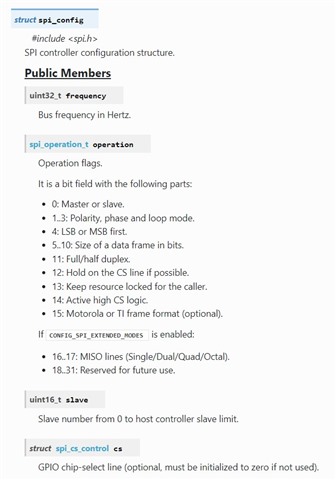
static struct spi_config spi_cfg = {
.frequency = 1000000, // SPI frequency.
.operation = SPI_OP_MODE_MASTER | SPI_WORD_SET(8) | SPI_TRANSFER_MSB, // SPI Mode 0
.slave = 0, // Master mode
.cs = NULL,
//.cs = &spi_cs, // Manage CS pin with cs-gpios in Devicetree
};
/* RHD2000 command definitions (16-bit) */
#define RHD_CMD_CONVERT(channel) (uint16_t)((((uint16_t)(channel) & 0x3F) << 8))
// Input: 00RR RRRR 0000 0000
// Output: DDDD DDDD DDDD DDDD
#define RHD_CMD_WRITE(reg, data) (uint16_t)(0x8000 | (((uint16_t)(reg) & 0x3F) << 8) | ((uint16_t)(data) & 0xFF))
// Input: 10RR RRRR DDDD DDDD
// Output: 1111 1111 DDDD DDDD , D: same with input's D (for confirm)
#define RHD_CMD_READ(reg) (uint16_t)(0xC000 | (((uint16_t)(reg) & 0x3F) << 8))
// Input: 11RR RRRR 0000 0000
#define RHD_CMD_CALIBRATE (uint16_t)(0x5500) // 0101 0101 0000 0000
#define RHD_CMD_DUMMY_READ RHD_CMD_READ(63) //
static int rhd_spi_transfer(uint16_t tx_command, uint8_t *rx_buffer) {
uint8_t tx_buffer[2];
// Convert 16-bit command to a Big-Endian byte array
tx_buffer[0] = (uint8_t)(tx_command >> 8); // MSB
tx_buffer[1] = (uint8_t)(tx_command & 0xFF); // LSB
const struct spi_buf tx_spi_buf = {
.buf = tx_buffer,
.len = sizeof(tx_buffer)
};
const struct spi_buf_set tx_spi_bufs = {
.buffers = &tx_spi_buf,
.count = 1
};
// Directly store received data in the rx_buffer passed from main
struct spi_buf rx_spi_buf = {
.buf = rx_buffer,
.len = 2
};
const struct spi_buf_set rx_spi_bufs = {
.buffers = &rx_spi_buf,
.count = 1
};
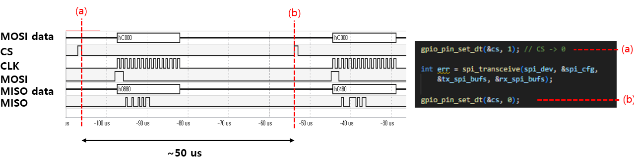
while (1) {
gpio_pin_set_dt(&cs, 1); // CS -> 0
int err = spi_transceive(spi_dev, &spi_cfg,
&tx_spi_bufs, &rx_spi_bufs);
gpio_pin_set_dt(&cs, 0);
return 0;
}
}
int main(void)
{
int ret;
int err;
ret = gpio_pin_configure_dt(&cs, GPIO_OUTPUT_INACTIVE);
gpio_pin_set_dt(&cs, 0); // I still don't understand why the output is 1 when 0 is passed to the set function.
if (!device_is_ready(spi_dev)) {
printk("SPI device %s is not ready!\n", spi_dev->name);
return 0;
}
if (!device_is_ready(uart_for_data_tx)) {
printk("UART device for data TX (%s) is not ready!\n", uart_for_data_tx->name);
return 0;
}
printk("nRF5340 SPIM example started.\n");
printk("Reading MISO pin (connected to DC voltage) and sending to PC via UART every second.\n");
uint8_t rx_main_buffer[2];
err = rhd_spi_transfer(RHD_CMD_WRITE(0, 0xDE), rx_main_buffer); // ADC configuration, disable fast settle
if (err) return err;
while (1) {
/* SPI communication (transceive) - send dummy bytes via MOSI to read MISO value */
rhd_spi_transfer(RHD_CMD_READ(0) , rx_main_buffer);
}
return 0;
};
app.overlay
/ {
chosen {
zephyr,console = &uart0;
zephyr,shell-uart = &uart0;
};
aliases {
spi4-basic = &spi4;
};
};
&uart0 {
status = "okay";
current-speed = <1000000>;
};
&pinctrl {
spi4_custom_pins: spi4_custom_pins {
group1 {
psels = <NRF_PSEL(SPIM_SCK, 1, 15)>,
<NRF_PSEL(SPIM_MOSI, 1, 14)>,
<NRF_PSEL(SPIM_MISO, 1, 13)>;
};
};
spi4_custom_pins_sleep: spi4_custom_pins_sleep {
group1 {
psels = <NRF_PSEL(SPIM_SCK, 1, 15)>,
<NRF_PSEL(SPIM_MOSI, 1, 14)>,
<NRF_PSEL(SPIM_MISO, 1, 13)>;
low-power-enable;
};
};
};
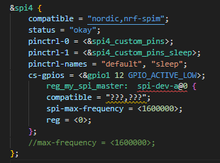
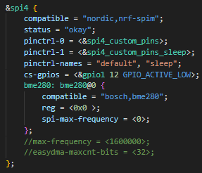
&spi4 {
compatible = "nordic,nrf-spim";
status = "okay";
pinctrl-0 = <&spi4_custom_pins>;
pinctrl-1 = <&spi4_custom_pins_sleep>;
pinctrl-names = "default", "sleep";
cs-gpios = <&gpio1 12 GPIO_ACTIVE_LOW>;
//max-frequency = <560000>;
//easydma-maxcnt-bits = <32>;
};
prj.conf
# enable console
CONFIG_CONSOLE=y
CONFIG_UART_CONSOLE=y

CONFIG_SERIAL=y
CONFIG_PRINTK=y


CONFIG_SPI=y

CONFIG_GPIO=y
In main.c, when I configure the SPI structure, I set the frequency to 1MHz.
I have confirmed with an oscilloscope that the actual clock frequency is indeed 1MHz.
Also, I'm controlling the CS pin directly via GPIO
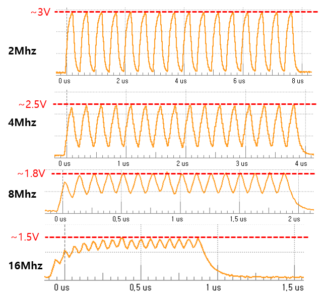
2. Although the nRF5340 specifications state that it supports SPI frequencies up to 8MHz (and even up to 32MHz for spi4),
the quality of the Clock (CLK) signal degrades significantly at frequencies higher than 4MHz.
Thank you.
Best regards,
gwan0624